Sunday, December 5, 2010

Presentation in College Station

On Friday December 3rd, we had an initial presentation in College Station. This allowed us to travel to meet our counterparts from Texas A&M. This was a fairly causal presentation. We switched with A&M architecture students and talked to them about our projects. Ron Skaggs from HKS (also an A&M alum) was able to come to our presentation and to discuss our specific project with us. Tomorrow, Monday December 6th, we will be presenting in North Tulsa near the actual project site. Below are photos from our display at the gallery at Texas A&M.


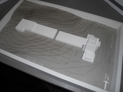
Our presentation includes a board for each rendered floor plan so that they can be seen at 1/8" scale. There are also boards for the key and site plan, the section perspectives, and some exterior perspectives. The trifold board contains all interior perspectives as well as additional exterior perspectives. We also have a materials board for the developed spaces. There is also a site model to show overall massing for the building. Visible in the last photo is a model of the sculptural piece that we designed for the atrium area. These are 1" acrylic cubes arranged so as to best capture the abundant natural light within the space and to create prisms.

Monday, November 22, 2010

Progress: Renderings, Floor Plans, The Project Book

Our group has been working diligently on preparing everything for the final presentations. Rendered floor plans have been completed in photoshop. Interior perspectives from 3ds Max have been completed. Exterior perspectives from Revit have been completed. Now, it's all in the details. The architects are working on a model of the site, which includes a massing model of our building. They are also building a model of our custom sculpture. The interior designers are putting together the materials and presentation boards and working on the project booklet. This will include information on process, precedent studies, materials, furniture, all renderings, floor plans, occupancies, etc. Below are a few images of our progress. Please note that final touches have not been put on any of these images.

RENDERED FLOOR PLANS:
Spaces undeveloped on each floor are shaded in grey. The floor plans will be superimposed onto the site via an arial view for the final presentation.


INTERIOR RENDERINGS:
These images are taken directly from 3ds Max. They do not include final details, such as accessories, silhouettes, exterior views, finalized lighting, etc.


ATRIUM: This view is northeast facing. The central piece is the canteen in this image. The connection to the second floor through the open central area is also visible. The bank of elevators as well as the staircases are visible to the right and create a focal point in this perspective.


ATRIUM: This is a view of our community communication area. It includes two digital kiosks as a guest resource. This custom wall (the other side faces the entrance) is made completely of cork. This will serve as a place to put fliers containing information about various events in the community.


SPECIALTY CLINIC: This is a simple view of an exam room. It will include silhouettes depicting a doctor and patient as well as the necessary accessories.


Monday, November 15, 2010

The Final Stages

We're getting close to the end, which is the most exciting part of the project. The architects have laser cut the site and are assembling the entire site model. We're also in the process of cutting out acrylic to make a model of the sculpture in the atrium. Interiors are focusing on rendering now, both the perspectives (using 3ds Max) and the floorplans (using photoshop).

Following are some perspectives that the architects have been working on in Rhino to understand the exterior materials better. Visible in these models are the major window placements. The first photo shows the best representation of exterior materials to be used. The east and west perspectives show a better understanding of the roof volumes as well as the integration of windows into the atrium space.


The interior designers have set up several cameras in AutoCad to determine where perspectives will be. Those images follow. Please note that the colors are from AutoCad layers and do not reflect the true materials to be applied in 3ds Max.

This perspective is in the atrium area. It showcases the canteen, which was a custom design, and the elevator/stair area. Visible in the corner is the relationship to the second and third floors, because the central atrium space is open to below.

This perspective is also in the atrium area. It showcases the greeter desk, another custom design.The canteen is visible in the background of this space. Atrium seating is also visible. The wall behind the greeter desk is make completely of cork. The curved piece at the top will hold the name of the building: Wayman Tisdale Community Wellness Complex. The backside of the wall faces the guest resource information kiosk. It also functions as a pin-up board for community flyers and events.


This is a perspective of the wellness center. The foreground shows the deli/smoothie bar area that connects the fitness center and the auditorium. This is another custom piece. The background will display exercise equipment, which will be added in 3ds Max. The wall of windows in the background faces the street on the east side of the building.


This perspective is of a mostly empty space, but we wanted to show it to convey the connection in this area. This is also the wellness center. This view is from the fitness area (which will have exercise equipment) into the group fitness group (for yoga, Zumba, etc.) Once blocks are added in 3ds Max and silhouettes added in Photoshop, this will become a very dynamic perspective view.

Monday, November 8, 2010

It's All Starting to Come Together

We decided to separate these blog posts so as not to have to cram so much information into the same post. This post includes several exterior perspectives from sketchup that show some preliminary exterior materials, as well as the incorporation of windows into the shell of the building. Additionally, the interior designers have designed several custom pieces for the interior, including the greeter desk, the deli/smoothie bar, and the canteen. They will also be designing and modeling a sculpture for the Lobby/Atrium. Look for that to be added soon.


NORTH
 EAST
 SOUTH
 WEST
 NORTHEAST
 SOUTHEAST
 SOUTHWEST
 NORTHWEST

Instead of placing pre-fab pieces in for all of the furniture, we decided to design custom pieces for several areas that could follow with our overall design philosophy of the building. Because "blocks" are our overarching theme, we wanted to keep that shape fairly consistent. However, we don't want all the pieces to look exactly the same or to be too literal in their interpretation of the theme.

CANTEEN: This area is located in the lobby/atrium as a food service area.

 FRONT VIEW

 PERSPECTIVE


Deli/Smoothie Bar: This area is located in the wellness center and is intended as a place to pick up a healthy snack or meal before or after a workout. It is also adjacent to the auditorium and serves as a snack bar for that area.
 FRONT VIEW

 PERSPECTIVE


Greeter Desk: This is the first sight upon entering the building. It features a desk for a receptionist. The wall also has signage with the name of the medical complex. This wall is built completely of cork, and the back side of it serves as a community memo board.
 FRONT VIEW

PERSPECTIVE

Site, Structural Gride, Finalizing the Mass

We have accomplished a great deal in the past week. This will allow us a significant amount of time for finishing touches in the coming weeks. Upcoming goals include selecting and modeling perspectives for interiors, and landscape/surrounding area development for the architects.

First are more detailed images of our site development and analysis of the topography of the site.


Next are process images of the development of the parking lot area that is to serve both our building and the existing strip mall.


Next the architects focused on creating the structural grid for the building. When consulting their structures teacher, our architects found that certain cantilevered aspects of our building would not be structurally sound. This led to the reimagining of several spaces to keep the same overall feel of the building while incorporating a sound structural grid. Following are sketches of the options and trials of the grid system.


After pinning down the final structural grid, several changes needed to be made to the floor plans. Most of the blocks needed to be altered at least slightly to accommodate these changes. Process of floor plan changes follow.


Finalizing the structure and layout of the building allowed the architects to fully focus on the exterior massing and details.


Look to our next post for sketchup images of the building as well as images of the custom pieces being designed for several interior areas.